
Higher-end sensor where higher accuracy is required


Overview
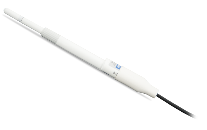
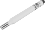
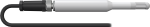
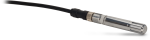
The HMP155A provides reliable relative humidity (RH) and temperature measurements for a wide range of applications. It uses a HUMICAP®180R capacitive thin film polymer sensor to measure RH over the 0 to 100% RH range. A PRT measures temperature over the -80° to +60°C range. This rugged, accurate temperature/RH probe is manufactured by Vaisala.
Read MoreBenefits and Features
- Well-suited for long-term, unattended applications
- Accurate and rugged
- Mounts to a mast, crossarm, or user-supplied pole
- Compatible with most Campbell Scientific data loggers
Images
Detailed Description
To reduce the current drain, power can be supplied to the HMP155A only during measurement when the sensor is connected to the data logger’s switched 12 V terminal. Data loggers that do not have a switched 12 V terminal, such as the CR510 or CR7, can use the SW12V switched 12 V device to switch power to the sensor only during measurement.
Specifications
| Electromagnetic Compatibility | Complies with EMC standard EN61326-1 Electromagnetic |
| Filter Description | Sintered PTFE |
| Housing Body Material | PC |
| Housing Classification | IP66 |
| Voltage Output | 0 to 1 Vdc |
| Average Current Consumption | ≤ 3 mA (analog output mode) |
| Operating Voltage | 7 to 28 Vdc |
| Settling Time | 2 s (at power up) |
| Field-Replaceable Chip or Recalibrate | Recalibrate |
| Tip Diameter | 1.2 cm (0.5 in.) |
| Length | 27.9 cm (11 in.) |
| Head Height | 4 cm (1.6 in.) |
| Body Height | 2.4 cm (0.9 in.) |
| Body Width | 2.0 cm (0.8 in.) |
Relative Humidity |
|
| Sensing Element | HUMICAP 180R |
| Measurement Range | 0 to 100% RH (non-condensing) |
| Response Time |
|
| Factory Calibration Uncertainty |
|
| Accuracy |
|
Air Temperature |
|
| Sensing Element | PT 100 RTD 1/3 class B IEC 751 |
| Measurement Range | -80° to +60°C |
| Accuracy |
|
| Entire Temperature Range | Refer to graph in probe manual. |
Compatibility
Note: The following shows notable compatibility information. It is not a comprehensive list of all compatible or incompatible products.
Data Loggers
| Product | Compatible | Note |
|---|---|---|
| CR1000 (retired) | ||
| CR1000X | ||
| CR300 | ||
| CR3000 (retired) | ||
| CR310 | ||
| CR350 | ||
| CR6 | ||
| CR800 (retired) | ||
| CR850 (retired) |
Additional Compatibility Information
Sensor Mounts
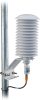
When exposed to sunlight, the HMP155A must be housed in a 41005-5 or RAD14 14-plate naturally aspirated radiation shield. The 41005-5 and RAD14 attach to a crossarm, mast, or user-supplied pipe with a 2.5 to 5.3 cm (1.0 to 2.1 in.) outer diameter. The RAD14 uses a double-louvered design that offers improved sensor protection from driving rain, snow, and insect intrusion, It also has lower self-heating in bright sunlight combined with higher temperatures (> 24°C [~75°F])
and low wind speeds (< 2 m s-1 [~4.5 mph]), giving a better measurement.
Documents
Technical Papers
Downloads
HMP155A Example Programs (4 KB) 10-15-2021
Description: Example CR1000X programs that measure either the analog voltage or RS-485 output of the HMP155A. The analog voltage programs use either the VoltSE or VoltDiff instruction and switch power to the sensor only during measurements. One program also calculates the mean vapor pressure. The RS-485 program measures the RS-485 output with an SDM-SIO1A/SIO4A. Although these programs are written for the CR1000X, programs for other dataloggers will be similar.
Frequently Asked Questions
Number of FAQs related to HMP155A-L: 7
Expand AllCollapse All
-
The maximum cable length is 304 m (1000 ft).
-
No. The HMP155A-L requires the 41005-5 14-Plate Solar Radiation Shield.
-
Most Campbell Scientific sensors are available as an –L, which indicates a user-specified cable length. If a sensor is listed as an –LX model (where “X” is some other character), that sensor’s cable has a user-specified length, but it terminates with a specific connector for a unique system:
- An –LC model has a user-specified cable length for connection to an ET107, CS110, or retired Metdata1.
- An –LQ model has a user-specified cable length for connection to a RAWS-P weather station.
If a sensor does not have an –L or other –LX designation after the main model number, the sensor has a set cable length. The cable length is listed at the end of the Description field in the product’s Ordering information. For example, the 034B-ET model has a description of “Met One Wind Set for ET Station, 67 inch Cable.” Products with a set cable length terminate, as a default, with pigtails.
If a cable terminates with a special connector for a unique system, the end of the model number designates which system. For example, the 034B-ET model designates the sensor as a 034B for an ET107 system.
- –ET models terminate with the connector for an ET107 weather station.
- –ETM models terminate with the connector for an ET107 weather station, but they also include a special system mounting, which is often convenient when purchasing a replacement part.
- –QD models terminate with the connector for a RAWS-F Quick Deployment Station.
- –PW models terminate with the connector for a PWENC or pre-wired system.
-
Not every sensor has different cable termination options. The options available for a particular sensor can be checked by looking in two places in the Ordering information area of the sensor product page:
- Model number
- Cable Termination Options list
If a sensor is offered in an –ET, –ETM, –LC, –LQ, or –QD version, that option’s availability is reflected in the sensor model number. For example, the 034B is offered as the 034B-ET, 034B-ETM, 034B-LC, 034B-LQ, and 034B-QD.
All of the other cable termination options, if available, are listed on the Ordering information area of the sensor product page under “Cable Termination Options.” For example, the 034B-L Wind Set is offered with the –CWS, –PT, and –PW options, as shown in the Ordering information area of the 034B-L product page.
Note: As newer products are added to our inventory, typically, we will list multiple cable termination options under a single sensor model rather than creating multiple model numbers. For example, the HC2S3-L has a –C cable termination option for connecting it to a CS110 instead of offering an HC2S3-LC model.
-
Note the difference between calibration and a field check. Calibration cannot be done in the field, as it requires an experienced technician and specialized equipment.
Field checks of measurements can be done to determine if the data make sense with the real-world conditions. Follow these steps to field check a sensor:
- Find a second sensor of the same type as the installed sensor whose data is in question. The second sensor will be used as a benchmark sensor and should be known to be accurate or recently calibrated.
- At the site, take readings using both sensors under the same conditions. The best practice is to measure both sensors side-by-side at the same time. Note that the sensors will never have the exact same measurement.
- Depending on the sensor model, if the difference in the readings of the installed and benchmark sensors is greater than the sum of the accuracies for both sensors, either return the installed sensor to Campbell Scientific for calibration or replace the appropriate chip.
- The 107, 108, 109, 110PV-L, and BlackGlobe-L temperature sensors can be calibrated.
- The HC2S3-L and HMP155A-L temperature and relative humidity sensors can be calibrated.
- The CS215-L has a replaceable chip for temperature and relative humidity. For more information, refer to the “Maintenance and Calibration” section of the CS215 instruction manual.
- The HMP60-L has a replaceable chip for relative humidity only. For more information, refer to the “Maintenance” section of the HMP60 instruction manual.
-
Many Campbell Scientific sensors are available with different cable termination options. These options include the following:
- The –PT (–PT w/Tinned Wires) option is the default option and does not display on the product line as the other options do. The cable terminates in pigtails that connect directly to a data logger.
- In the –C (–C w/ET/CS110 Connector) option, the cable terminates in a connector that attaches to a CS110 Electric Field Meter or an ET-series weather station.
- In the –CWS (–CWS w/CWS900 Connector) option, the cable terminates in a connector that attaches to a CWS900-series interface. Connection to a CWS900-series interface allows the sensor to be used in a wireless sensor network.
- In the –PW (–PW w/Pre-Wire Connector) option, the cable terminates in a connector that attaches to a prewired enclosure.
- In the –RQ (–RQ w/RAWS Connector) option, the cable terminates in a connector that attaches to a RAWS-P Permanent Remote Automated Weather Station.
Note: The availability of cable termination options varies by sensor. For example, sensors may have none, two, or several options to choose from. If a desired option is not listed for a specific sensor, contact Campbell Scientific for assistance.
-
Single-ended channels are typically used when it is desirable to use fewer channels and the cable length is shorter—less than 6.1 m (20 ft). Differential channels are preferable when the cable needs to be longer than 6.1 m (20 ft).
Case Studies
Overview In the fight against climate change, innovative solutions are emerging to address the global challenge......read more
Overview In May 2019, the Government of Zambia embarked on the Central Asia Water & Energy......read more
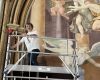
Overview The Royal Chapel of Chaalis Abbey—often referred to as the “French Sistine Chapel”—is a treasure......read more
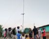
Overview As part of the United Nations Development Programme's (UNDP) Climate Adaptation Water and Energy Programme......read more
Overview The Kingdom of eSwatini in Southern Africa—with its agricultural-based economy and a population of less......read more
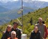
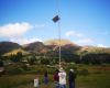
Introduction The Andes Mountains of Argentina are home to a rich and diverse group of organic......read more
Privacy Policy Update
We've updated our privacy policy. Learn More
Cookie Consent
Update your cookie preferences. Update Cookie Preferences