UT30

UT30
Orderable30 ft Universal Tower with Adjustable Mast
Overview
The UT30 is a durable instrument tower that can be used for a variety of applications. The UT30 tower provides a sturdy mount for many meteorological monitoring applications—especially air quality stations and regional Mesonets, where the 10 m (32.81 ft) measurement height for wind sensors is standard. It also holds antennas, solar panels, environmental enclosures, radiation shields, and crossarms. It is a versatile instrument mount: many of the same sensor mounts that are used with either our tripods or other towers can be used with the UT30.
Technical Description
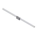
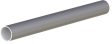
The UT30 tower includes three 3 m (10 ft) sections and one extendable mast. The extendable mast has a 1.5 m (5 ft) length and a 3.175 cm (1.25 in) outer diameter [swagged to 2.5 cm (1 in) OD].
Top 3 m Section
The top section is constructed from 2.5 cm (1 in) OD aluminum tubing. Its width is 25.7 cm (10.1 in) on a side (center of tubing to center of tubing).
Center 3 m Section
The center section is constructed from 2.5 cm (1 in) OD aluminum tubing. Its width is 33.3 cm (13.1 in) on a side (center of tubing to center of tubing).
Bottom 3 m Section
The bottom section is constructed from 3.175 cm (1.25 in) OD aluminum tubing. Its width is 43.2 cm (17 in) on a side (center of tubing to center of tubing).
Mounting Base, Grounding Kit, and Guying Kit
This tower requires a mounting base and grounding kit. Campbell Scientific also recommends guying the UT30 with our UTGUY Guy Kit. See Ordering Info on the web page for more information.
Benefits
- Sturdy, long-term instrument mount
- Corrosion-resistant
Specifications
- Material
- Hardened drawn 6063-T832 aluminum
- Guyed Tower Area Requirements
- ~5 m
(17 ft) radius
- Required Concrete Pad Dimensions
- 91 x 91 x 122 cm
(36 x 36 x 48 in.) for B18 Concrete Mounting Base
Concrete pad requirements assume heavy soil; light, shifting, or sandy soils require a larger concrete pad. - Extendable Mast
- 1.5 m (5 ft) length3.175 cm (1.25 in.) outer diameter
(swagged to 2.5 cm [1 in.] outer diameter)
- Pipe Outer Diameter
- 2.5 cm
(1.0 in.) for vertical tubing of upper sections
3.18 cm(1.25 in.) for vertical tubing of lower section
0.953 cm(0.375 in.) for cross supports/webbing
- Crossarm Measurement Height
- 10 m
(33 ft)
- Height
- 10.1 m
(33 ft)
- Shipping Dimensions
- 310 x 46 x 46 cm
(122 x 18 x 18 in.)
- Shipping Weight
- 29 kg
(65 lb)
Maximum Wind Load Recommendation
- B18 Base (unguyed)
- 177 km/h
(110 mph)
- RFM18 Base (with UTGUY)
- 177 km/h
(110 mph)
- UTBASE (unguyed)
- 177 km/h
(110 mph)
- -NOTE-
- Wind load endurance is affected by quality of anchoring and installation; guy wire tension; soil type; guy angle; and number, type, and location of instruments fastened to the tower.
Wind load recommendation assumes proper installation, proper anchoring, adequate soil, and total instrument projected area of less than 0.19 m2 (2 ft2) at the height of the tower.
For the RFM18 base, the wind load recommendation also assumes that the UTGUY’s turnbuckles are preloaded just enough to equalize tension and that the tower is guyed at a 60 degree angle relative to the ground (maximum).
Accessories
(7)UTBASE
Base Kit for UT20/UT30
OrderableB18
Concrete Mounting Base for UT20 and UT30
OrderableUTGND
Universal Tower Grounding Kit
OrderableUTGUY
Universal Tower Guy Kit
OrderableUTGUYSS
Stainless-Steel Universal Tower Guy Kit
OrderableCM204
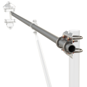
4 ft Crossarm with One CM210 Mounting Kit
OrderableCM206
6 ft Crossarm with One CM210 Mounting Kit
Orderable
Common Accessories
(7)UTBASE
Base Kit for UT20/UT30
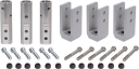
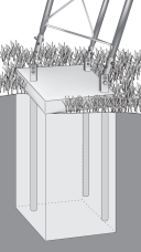
The UTBASE is designed to provide a simpler, easier installation method for 6 m and 10 m (20 ft and 30 ft) towers. The UTBASE eliminates the need for you to install bolts and the lower tower section, as you only need to install bolts in the concrete. By using the optional template, you can ensure that the bolt spacing is initially correct and maintained while the concrete cures. In addition, the template allows room for you to embed conduit in the concrete if desired. You can also adjust the UTBASE after the concrete has cured to ensure that the tower is true/plumb.
OrderableB18
Concrete Mounting Base for UT20 and UT30
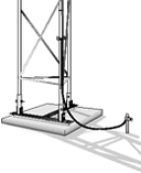
The user embeds this base in concrete. When using the B18 base, our UTGUY Tower Guy Kit is recommended.
OrderableUTGUY
Universal Tower Guy Kit
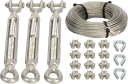
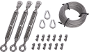
This kit includes a 1/8" diameter, galvanized steel cable, thimbles, U-bolts, and tightening turnbuckles for use with the UTDUK or UTEYE anchors.
OrderableUTGUYSS
Stainless-Steel Universal Tower Guy Kit
The UTGUYSS is a 316 stainless-steel version of the UTGUY Universal Tower Guy Kit for use in mounting a tower when additional corrosion resistance is needed. Earth anchors such as the UTDUK or UTEYE are required. While the UTDUK and UTEYE will work with the UTGUYSS, note that these anchors are not constructed of stainless steel.
OrderableUTGND
Universal Tower Grounding Kit
This kit consists of a lightning rod, ground rod, and components to connect the datalogger enclosure and tower to the ground rod. It is required.
OrderableUTDUK
Duckbill Anchors for UTGUY (set of 3)
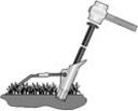
The UTDUK includes a drive bar [#6136] and three Duckbill guy anchors [#6135] for use in non-rocky soils. It is used with the UTGUY guy kit.
OrderableUTEYE
Eyebolt Anchors for the UTGUY (set of 3)
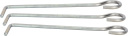
The UTEYE consists of three eyebolt guy anchors [#5443] that embed in concrete. It is used with the UTGUY guy kit.
Orderable
Other Accessories
(2)7364
UV-Resistant 8 in. Cable Ties (quantity of 12)
The kit includes 12 Tefzel® 8 in. cable ties (pn 7362) that are resistant to gamma radiation, UV radiation, and chemicals.
Orderable39572
UV-Resistant 18 in. Cable Ties (quantity of 10)
The 39572 includes 10 of the 45.7 cm (18.1 in.) black, UV-resistant cable ties (pn 39333). These cable ties are often used with tripods and towers, and this 10-unit pack can be purchased as a replacement item. A connection is made by pulling the tapered end through the locking end, thus forming a loop. The free end is pulled tight to secure the cable tie, then trimmed back to the locking end. Once attached, the cable tie must be cut to be removed.
Orderable




Compatibility
Enclosure Brackets
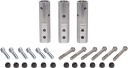
The “-TM” mount option for our environmental enclosures is used to attach our enclosures to a UT30 tower. An enclosure ordered with the “-TM” option will be shipped with a three-piece bracket mounted to the top of the enclosure and an identical three-piece bracket mounted to the bottom of the enclosure. This mounting bracket option uses the same three-piece brackets as the "-MM" option, except the pieces are rearranged so that the flanges are on the side of the bracket instead of in the middle. The distance between the centers of each flange needs to be 17”.
Note:
Enclosures with the "-TM" option are shipped configured for the UT10 tower. UT30 customers will need to: (1) remove the bolts attaching the bracket to the enclosure, (2) slide out the flange sections so that the distance between the center of each flange is 17", and (3) reattach the bracket to the enclosure using the original bolts.
Compatible Products
(6)CM202
2 ft Crossarm with One CM210 Mounting Kit
OrderableNotes—CM202SS
2 ft Stainless-Steel Crossarm with One CM210 Mounting Kit
OrderableNotes—CM203
3 ft Crossarm with One CM210 Mounting Kit
OrderableNotes—CM204
4 ft Crossarm with One CM210 Mounting Kit
OrderableNotes—CM204SS
4 ft Stainless-Steel Crossarm with One CM210 Mounting Kit
OrderableNotes—CM206
6 ft Crossarm with One CM210 Mounting Kit
OrderableNotes—
Related Resources
Case Studies
West Texas Mesonet
Providing free real-time weather and agricultural information
Texas, USA
May 14, 2009
View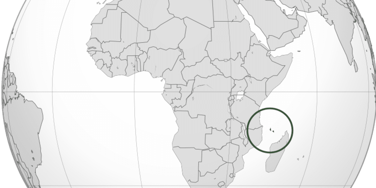
Union of the Comoros: Establishment of Four Weather Stations for Better Resilience to Climatic Hazards
Monitoring an area prone to seasonal cyclones
The Union of the Comoros, East Africa
January 14, 2022
View