AVW200

AVW200
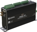
Orderable2-Channel Vibrating Wire Analyzer Module
Pricing
Request a quote Have pricing access? Sign in
Configuration
- -25 to +50C (Ships as 19244, 19246, & 10873)AVW200-STPart Number: 42055
- -55 to +85C (Ships as 33939, 19246, & 10873)AVW200-XTPart Number: 42056
Select a configuration to add to your quote
- Model:
- AVW200
- Item Number:
- AVW200
- Warranty:
- 1 year
Overview
With an AVW200 vibrating wire analyzer module, your data logger can measure vibrating wire strain gages, pressure transducers, piezometers, tiltmeters, crackmeters, and load cells. These sensors are used in a wide variety of structural, hydrological, and geotechnical applications because of their stability, accuracy, and durability.
Learn about our patented VSPECT™ spectral-analysis technology at our VSPECT Essentials web resource.
The dynamic vibrating wire measurement technique is protected under U.S. Patent No. 8,671,758, and the vibrating wire spectral-analysis technology (VSPECT) is protected under U.S. Patent No. 7,779,690.
Key Advantages
Using patented VSPECT® technology for better readings
Technical Description
The AVW200 uses vibrating wire spectral-analysis technology (VSPECT). VSPECT observes the incoming sensor signal, performs a Fourier transform and a spectral analysis (transforming the time series into individual sinusoidal components in the frequency spectrum), and determines the sensor frequency by identifying the largest signal in the acceptable range while filtering out environmental and electrical noise.
The AVW200 analyzer module also provides many self-checking diagnostics such as vibrating element signal strength, signal-to-noise ratio, vibrating element signal decay ratio, and incorrect signal response. These diagnostics can be running in the background to give continual feedback of the condition for each sensor.
Benefits
- Provides better measurements by significantly reducing incorrect readings caused by noise sources
- Interfaces two vibrating wire sensors; more sensors may be connected if an AM16/32B multiplexer is used
- Self-checking diagnostics give continual feedback on sensor condition
- High resolution—less than 0.001 Hz (industry standard is 0.1 Hz)
- Low current drain
- Interfaces both temperature and frequency measurements from vibrating wire sensors
Specifications
- -NOTE-
- Electrical specifications are valid over a -25° to +50°C range unless otherwise specified.
Non-condensing environment required.
- Number of Vibrating Wire Sensors Measured
- Up to 2 vibrating wire sensors can be connected to the analyzer module.
Additional sensors can be measured by using an AM16/32-series multiplexer.
- Power Requirements
- 9.6 to 16 Vdc
- Analog Input/Outputs
- 2 differential (DF) vibrating wire measurements (V+ and V-) and 2 single-ended (SE) ratiometric resistive half-bridge measurements (T+ and T-) for vibrating wire sensor's onboard temperature sensor.
- Digital Control Ports
- 3 digital control ports (C1 – C3)
C1 functions as an SDI-12 I/O communication port.C2 functions as a Clk output for multiplexer control.C3 functions as a Reset output for multiplexer control.
- RS-232 Port
- 1 9-pin RS-232 port
(for connecting to a data logger COM port)
- Measurement Resolution
- 0.001 Hz RMS
(±250 mV differential input range; -55° to +85°C)
- Measurement Accuracy
- ±0.013% of reading
(±250 mV differential input range; -55° to +85°C)
- Input Voltage Range
- ±250 mV
(differential) for vibrating wire inputs
- Common Mode Range
- ±25 V
- Baud Rates
- Selectable from 1200 to 38.4 kbps.
(ASCII protocol is one start bit, one stop bit, eight data bits, and no parity.)
- Memory
- Either 128 or 512 kB of SRAM2 MB of OS Flash
- CE Compliance Standards to which Conformity Is Declared
- IEC61326:2002
- Dimensions
- 21.6 x 11.18 x 3.18 cm
(8.5 x 4.4 x 1.25 in.)
- Weight
- 0.43 kg
(0.95 lb)
Typical Current Drain @ 12 Vdc
- Quiescent, Radio Off
- ~0.3 mA
- Radio Duty Cycling 1 s
- ~3 mA
(includes quiescent current)
- Radio Always On
- ~26 mA
(radio transmit current 100 mA)
- Active RS-232 Communication
- ~6 mA
(3 s after communication stops, the current will drop to the quiescent current.)
- Measurement
- ~25 mA
(averaged over the 2 s)
Common Accessories
(4)CABLE3CBL
3-Conductor 22 AWG Cable with Drain
The CABLE3CBL is recommended to connect the AVW200 to a datalogger when SDI-12 is used. This 22 AWG, three-conductor cable has a Santoprene jacket and an aluminum Mylar shield.
Orderable18663
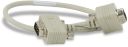
Null Modem Cable, 9-Pin PIn (Male) to 9-Pin Pin (Male)
This 1-ft, null modem cable has 9-pin connectors on both ends. The 18663 can connect the AVW200's RS-232 port to the datalogger's RS-232 port.
Orderable17855
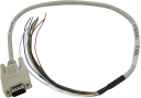
Serial Cable, DB9 Pin (Male) to Pigtail
One end of this cable is fitted with a 9-pin connector, and the other end terminates in pigtails. The 17855 is used to connect the AVW200's RS-232 port to a pair of control ports on a CR800, CR850, CR1000, or CR3000.
Orderable17394
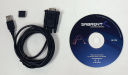
Converter, USB to DB9 Pin (Male) RS-232
The 17394 is a six-foot interface cable fitted with a USB connector on one end and a 9-pin pin (male) RS-232 connector on the other end. The USB connector attaches to the USB port of a PC. The RS-232 connector attaches to the RS-232 port of a data logger or peripheral, such as an MD485 Multidrop Modem or RF401-series Spread-Spectrum Radio. Alternatively, the RS-232 connector can attach to an SC32B interface, which attaches to the CS I/O port of a data logger via the SC12 cable
Orderable
Replacement Parts
(6)3768
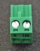
2-Pin Screw Terminal Plug Connector
This green, plug-in power connector is shipped attached to the AVW200. The 3768 provides screw terminals for connecting the 12V and GND wires of the 19246 power cable. The other end of the 19246 power cable connects to the 12V and G terminals of a datalogger or power supply.
Orderable20581
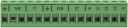
Green Terminal Connector Plug
The 20581 provides screw terminals for connecting the sensor(s) and multiplexer(s) to the AVW200. This green, plug-in connector may be purchased to have a spare terminal strip or as a replacement item if the strip has been lost or damaged.
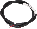
Orderable19246
Power Cable, AVW200-Series to Datalogger
The 19246 connects the AVW200 with the 12V and G terminals of a datalogger or power supply. This screw terminal is shipped with the AVW200 and available as a replacement part.
Orderable10873
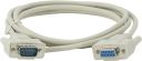
Serial Data Cable, 9-Pin Socket (Female) to 9-Pin Pin (Male)
This RS-232 cable connects the AVW200 with a PC. The AVW200 is connected to a PC during configuration and troubleshooting. The 10873 is shipped with the AVW200 and available as a replacement part.
Orderable6044
Grommet for #6 or #8 Screw
These grommets are commonly used with the 505 screws to secure our equipment to the backplates of our enclosures.
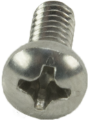
Orderable505
Screw #6-32 x .375 Pan Phillips
These screws, along with the 6044 grommets, are commonly used together to secure our equipment to the backplates of our enclosures.
Orderable
Similar Products
(5)AVW206
900 MHz Wireless 2-Channel Vibrating Wire Analyzer Module
Limited availabilityAVW216
2.4 GHz Wireless 2-Channel Vibrating Wire Analyzer Module
Limited availabilityCRVW3
Vibrating Wire Node
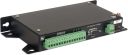
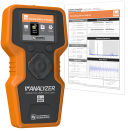
OrderableVWAnalyzer
Vibrating Wire Analyzer
OrderableGranite VWire 305
8-Channel Dynamic Vibrating Wire Analyzer
Orderable

Compatibility
Sensors
The AVW200 Vibrating Wire Spectrum Analyzer Module allows our data loggers to measure vibrating wire strain gauges, pressure transducers, piezometers, tiltmeters, crackmeters, and load cells.
Data Logger Connections
When using SDI-12, a three-conductor cable is required; Campbell Scientific recommends the CABLE3CBL cable. When using RS-232, the module attaches to the data logger’s RS-232 port via the 18663 null modem cable, or attaches to control ports on a CR800, CR850, CR1000, or CR3000 datalogger via the 17855 data cable.
Enclosure Considerations
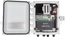
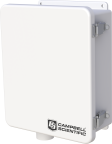
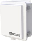
The AVW200 requires a desiccated, non-condensing environment. A Campbell Scientific enclosure is recommended when the analyzer module is in the field. The AVW200 has built-in keyhole flanges for mounting to an enclosure backplate.
Power Considerations
The AVW200 is typically powered by the data logger's power supply.
Compatible Products
(11)CR310
Measurement and Control Datalogger
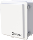
OrderableNotes—ENC10/12
Weather-Resistant Enclosure, 10 x 12 inches
OrderableNotesIf using the RS-232 port, the AVW200 must be mounted flat to fit in an ENC10/12.
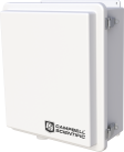
ENC10/12R
Raised Lid Enclosure, 10 x 12 inches
OrderableNotesIf using the RS-232 port, the AVW200 must be mounted flat to fit in an ENC10/12R.
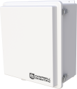
ENC12/14
Weather-Resistant Enclosure, 12 x 14 inches
OrderableNotesIf using the RS-232 port, the AVW200 must be mounted flat to fit in an ENC12/14.
ENC14/16
Weather-Resistant Enclosure, 14 x 16 inches
OrderableNotes—ENC16/18
Weather-Resistant Enclosure, 16 x 18 inches
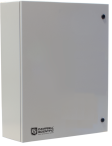
OrderableNotes—ENC24/30
Painted Steel Enclosure, 24 x 30 inches
OrderableNotes—ENC24/30S
Stainless-Steel Enclosure, 24 x 30 inches
OrderableNotes—CR350
Measurement and Control Datalogger
OrderableNotes—CR6
High-Capacity Data Acquisition System
OrderableNotesThe CR6 is compatible with the AVW200. However, because the CR6 has built-in vibrating wire measurement capabilities, the AVW200 is unnecessary.
CR1000Xe
Measurement and Control Datalogger
OrderableNotes—
Related Resources
Case Studies
Illinois: Automating a Data System
Automating data systems at construction site
La Grange, Illinois, USA
December 12, 2016
View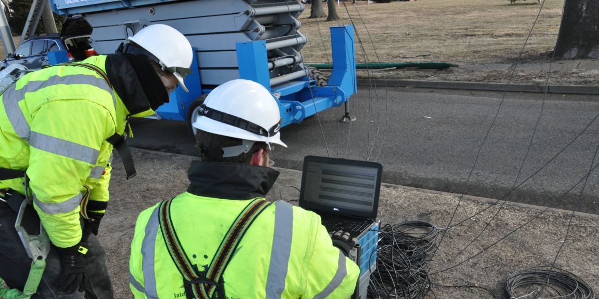
Delaware River: Bridge Health
Structural health monitoring
Bristol, PA; Burlington, NJ
December 29, 2017
View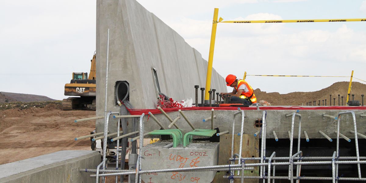
Utah: Monitoring Strain on Precast Bridge Deck
Monitoring strain on bridge deck
Beaver Creek Bridge on US 6 near Price, Utah
February 27, 2014
View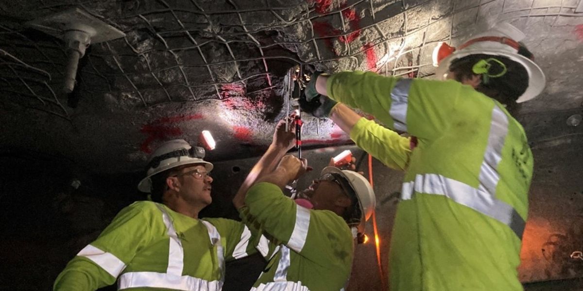
South Dakota: Rock Stability in Large Underground Excavation
Large-cavern, hard-rock excavation
Lead, South Dakota, USA
April 9, 2024
View
Showing 4 of 14 results
See all Case StudiesDocuments
- Manual
AVW200-series 2-Channel Vibrating Wire Spectrum Analyzer Modules
February 2025
View Document - Manual
AVW200 Series Product Manual (online)
February 2025
View Document - Compliance
AVW200 UK Declaration of Conformity
August 2022
View Document - Brochure
AVW200 2-Channel Vibrating Wire Analyzer Module
March 2026
View Document
Showing 4 of 6 results
See all DocumentsDownloads
- AVW200 OSv06Login required
June 10, 2016
OS and FirmwareCurrent AVW200 firmware. Use the Device Configuration Utility version 1.13 or greater to send firmware and to configure the AVW200.
- AVW200 Program Examplesv1Login required
January 31, 2025
Software ApplicationsExample programs for the AVW200 and AVW206. The examples demonstrate a direct RS-232 connection to the AVW200, a wireless connection to an AVW206, an SDI-12 connection to the AVW200 and using multiplexers with the AVW200.
Videos and Tutorials

Webinar | VSPECT™—Patented Spectral-Analysis Technology
May 28, 2021 (48:50)
Spectral analysis of vibrating wire sensors for accuracy, confidence, and trust
Watch
VSPECT™—Understanding the Basics
August 17, 2021 (3:10)
Animated VSPECT video
Watch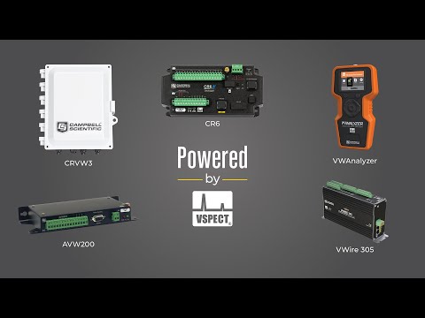
VSPECT™ vs. Noisy Data
July 23, 2025 (3:20)
Using VSPECT technology to filter electrical noise interference.
Watch
Early Warnings That Saved a Community
January 29, 2026 (3:36)
The Campbell Scientific flood warning system in Puerto Rico
Watch